
Develop the Wind Turbine example
In this section we will develop a simple Hello World-like application that demonstrates the major features of Cloudflow. It will not have many of the advanced features that Cloudflow offers—the main idea is to give you a feel for what it takes to build a complete application, run it locally, ant then deploy it in a GKE cluster.
Example Application Overview
The Wind Turbine application is a simple streaming pipeline that resembles the processing of events from a wind turbine farm. Each turbine has a unique ID and emits a time-stamped stream of events that contain measurements such as wind speed, rotor speed, and power produced.
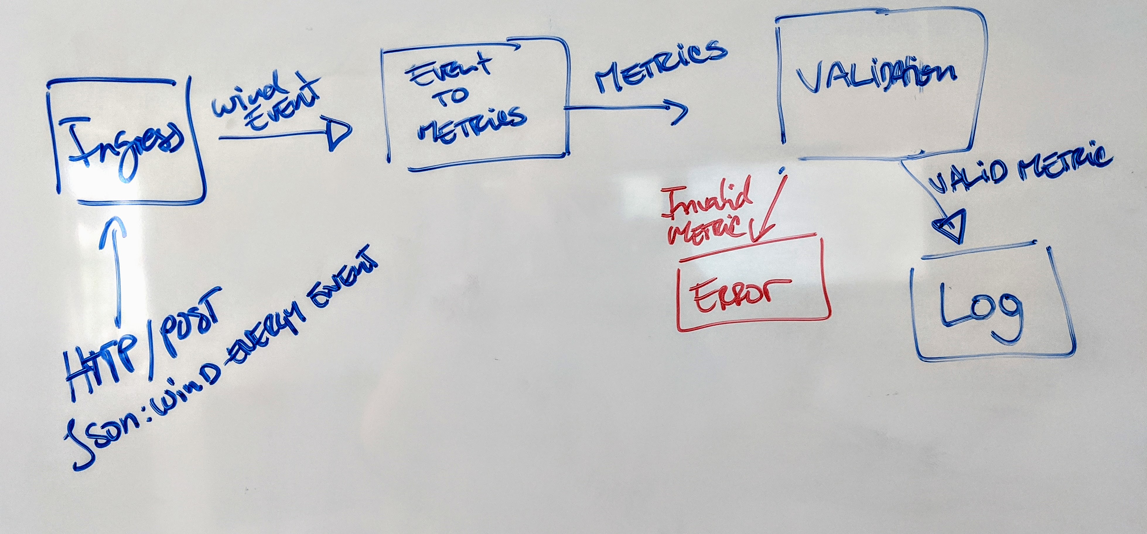
To make sure that the data flow is meaningful and correct, the streamlets in our application will: accept events, convert them into domain objects, validate them, and log them. The following illustrates the flow:
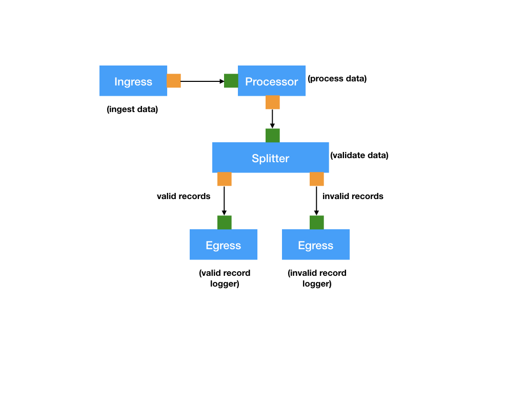
As shown in the image, streaming data will pass through the following transformations:
-
Ingestion by an Ingress streamlet: An Ingress streamlet has zero inlets and one or more outlets. It acquires data external to the application through some interface. For example, an ingress could be a server handling requests e.g. using HTTP. or connecting to an external Kafka broker. In this example, the
SensorDataHttpIngressingress is an HTTP server handlingHTTP/POSTrequests of wind turbine events encoded as JSON documents. -
Conversion by a Processor streamlet into a domain object: A Processor streamlet has one inlet and one outlet. Processors represent common data transformations like map and filter, or any combination of them. In this example, the
SensorDataToMetricsprocessor converts the event data intometricsthat can be further validated. -
Validation by a FanOut streamlet: A FanOut (also known as a Splitter) has one inlet and more than one outlet. The FanOut splits the input into multiple data streams depending on some criteria. The
MetricsValidationsplitter in this separates valid from invalid records. -
Logging Egress streamlet: An Egress represents data leaving the application. For instance this could be data being persisted to some database, notifications being sent to Slack, files being written to HDFS, etc. In this case, the streamlet will log the data to the console (standard output).
Development Overview
The development of a Cloudflow application typically starts by roughly defining the different blocks of the streaming pipeline, that we translate into streamlets, and the schema that they use to communicate between them.
Then, we formalize the schema definitions using AVRO, compile it, and use the generated types to represent the inputs and outputs of the streamlets. Let see how we do that in practice.
Schema-first Approach
In Cloudflow, the streamlet inputs and outputs are statically typed. The types represent events that the specific input/output can handle. The first step in application development is to encode these events in the form of an avro schema. Cloudflow will generate the appropriate classes corresponding to each schema.
Pipelines of Connected Components
One of the important features of Cloudflow architecture is the complete separation of the components from how they are connected as part of the pipeline. The streamlets described above are the individual building blocks of the pipeline. You can connect them using a declarative language that forms the blueprint of the pipeline. Streamlets can be shared across blueprints making them individual reusable objects. And just like streamlets, blueprints also form an independent component of a Cloudflow application.
This example demonstrates using Akka streamlets implemented in Scala. We’ll follow these steps: